- Ideal Mosfet Pspice
- Ideal Mosfet In Saturation
- Ideal Diode Circuit Mosfet
- Mosfet With Diode
- Ideal Mosfet
2N7000 N-Channel MOSFET
“Saving the subthreshold voltage loss allows the threshold voltage to approach the minimum threshold voltage of an ideal MOSFET, thereby enabling the scaling of supply voltage at fixed device performance,” he said. According to Wei Cao, the first author of the paper, and a member of Banerjee’s Nanoelectronics Research Lab, “the main. This course can also be taken for academic credit as ECEA 5632, part of CU Boulder’s Master of Science in Electrical Engineering degree. This course presents in-depth discussion and analysis of metal-oxide-semiconductor field effect transistors (MOSFETs) and bipolar junction transistors (BJTs) including the equilibrium characteristics, modes of operation, switching and current amplifying. IRFB7446PBF, StrongIRFET™ Power MOSFET, Infineon Infineon's StrongIRFET family is optimized for low R DS (on) and high-current capability. This portfolio offers improved gate, avalanche and dynamic.
Ideal general purpose switching MOSFET. Ideal for use in 3.3V and 5V applications
Typical On/Off Gate threshold voltage 2.1V. Rds of less than 5ohms

- Vgs On/Off = 2.1V (typ)
- Vgs max = +/- 18V
- Rds = 5ohms
- Continuous Current = 350mA
- Max peak Current = 1.4A
This mosfet is ideal for switching applications including LED's, logic inverter, 3.3V to 5V logic conversion.
This mosfet is not suitable for electric motors as its 5ohm on resistance is high compared to an electric motor.
Documents
- Manufacturer: ST Microelectronics
- Product Code: 2N7000
- Availability: 308
£0.18
- Ex Tax: £0.15
0 reviews / Write a review
Related Products
2N7002 - MOSFET, N-Channel, SMD SOT-23
2N7002 - MOSFET, N-Channel, SMD SOT-23 A useful general purpose Mosfet transistor in a surfac..
£0.10 Ex Tax: £0.08
There is nosuch thing as an ideal diode of course, but the following circuits canprovide a much closer approximation to diode ideality in ways that suitthe reverse current blocking requirements of certain power circuits. These are sometimes referred to as 'smart diodes'.
Oneapplication in mind is a battery charger. When charging from a sourcethat can drop below the battery voltage, there is a danger of thebattery discharging back through the charger and possibly damaging thelatter. As such a diode is usually inserted between the charger andbattery to block this reverse current flow. An ideal diode circuit maybe valuable in high power applications to reduce power and voltagelossesand heat dissipation demands.
Care needs tobe taken when considering its use innon-synchronous switch mode power supplies to replace a catch diode.The MOSFET takes a certain amount of time to turn on and off, and thismay result in destructive shoot through currents if other MOSFETs inthe circuit have turned on. In these cases it is preferable to make useof a synchronous mode circuit in which the controller inserts delays toavoid the situation.
Ideal Diodecontroller ICs are available from some manufacturers, for exampleLinear Technology and Maxim produce a small range of these that workwith or incorporate a power MOSFET, sensing the voltage across theMOSFET and turning it off when the voltage reverses. They can besomewhat expensive but can provide a range of additional safetyfeatures.
Ideal Diode Type 1
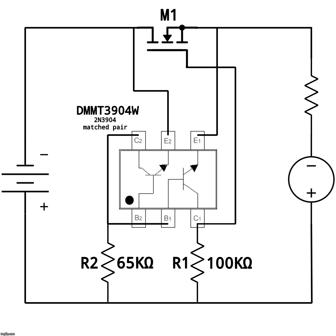
The followingcircuit only needs readily available BJTs and a handful of resistors,as well as the power MOSFET. It requires a supply to the BJTs that willallow the MOSFET gate-source voltage to be raised to a level to allowfull turn-on of the MOSFET. Ihaven't yet seen this particular circuit in the literature but it maywell exist. There are several forms of this circuit:this one places the MOSFET on the negative terminal of the battery.Other similar circuits are described below.
Thecircuit can be adapted easily enough to other topologies. To switch thepositive supply line the circuit can either use a P-type MOSFET and PNPBJTs, or use the same circuit as above in conjuction with an auxiliarylow power supply, such as a charge pump, to allow the BJTs to pull theMOSFET gate above its turn-on voltage.
How it Works
The MOSFET Q1is N-type in this circuit and operates in reverse mode, that is, itconducts when the drain-source voltage is negative. This voltage isintended to be less than the forward voltage of the body diode so thegate has control over its operation. If the current through the MOSFETis too high, the drain-source voltage may rise to the point where thebody diode turns on, which defeats the main purpose of the circuit.Therefore a MOSFET with a suitably low on-resistance needs to be chosento match the expected current load. The Schottky diode protects theMOSFET from large body diode currents during turn-on transients.
The circuittakes advantage of the strong dependence of BJT collector current onthe base-emitter voltage. Q3 clearly controls the gate voltage whilethe purpose of Q2 is to cancel the base-emitter voltage of Q3 and someasure the voltage difference across the MOSFET. If thevoltage across the MOSFET is positive, the emitter of Q2 rises aboveground, causing Q2 to turn off and Q3 to turn on. This pulls down thecollector of Q3 to turn off the MOSFET. Note that the base voltage ofQ3 can rise quite high, pushing it into saturation. However thisdoesn'tappear to affect the circuit operation greatly.
When thevoltage across the MOSFET goes negative, the emitter of Q2 is pulledbelow ground and Q3 starts to turn off. The MOSFET gate voltage risesuntil the MOSFET starts to turn on. The gate voltage settles at a pointwhich is just above the turn-on voltage. This will increase with draincurrent to keep the voltage drop across the MOSFET at a level thatactivates the BJTs.
The circuitdoesn't appear to be particularly sensitive (within limits) to thechoice of Q2, even if a different but similar transistor type is used.High gain BJTs will result in a smaller voltage across the MOSFET inthe on-state (and hence lower power loss). As such it was found thatSziklai and Darlington pairs could be made to work, although the higherbase-emitter voltage of the latter caused the circuit behaviour to bedegraded. To reduce the adverse effects of turn-on transients, highspeedswitching BJTs should be used (such as the 2N2222 used here).
It ispossible to improve the on-state drain-source voltage of the MOSFET byamplifying the gate signal with an operational amplifier between Q3 andthe MOSFET gate. A high speed operational amplifier with low outputimpedance needs to be chosen, and this introduces difficulties withinstability particulary at higher gains.
Ideal Diode Type 2
Acircuit offering the same functionality as the above is given inreference 1. This circuit uses a PNP-NPN pair of BJTs in aconfiguration whose operation is somewhat less transparent than the onedescribed above. The circuit below, based on this configuration, wastested with SPICE simulation. The connection between the BJTs is suchthat the PNP's base-emitter voltage cancels that of the NPN. When theMOSFET drain-source voltage drops below zero the PNP turns on andforces the NPN to turn off since its base-emitter voltage is tied tothat of the PNP's collector-emitter voltage. This turns off the MOSFET.
Thiscircuit amplifies the voltage across the MOSFET in a cascade pair ofBJTs, thus giving higher current gain than the circuit described above.Nevertheless the SPICE simulations show that thebehaviour of the circuit is almost identical to that of the circuit wepresented earlier, with a very similar on-state voltage across theMOSFET despite the high gain. In addition a significant amount ofoscillationoccurred when the MOSFET turned on. This may indicate that this circuitis less stable than the earlier one. Apossible cause of this oscillation may be due to the high gain, whichdid occur in our circuit when additional gain was added (although theSziklai and Darlingtonconfigurations did not show oscillations). A 100pF capacitor placedacross the base resistor Rp seemed to resolve the problem, at least asfar as simulation showed.
Ideal Diode Type 3
This isessentially the same circuit form as that used for type 1 butby making use of p-type MOSFET and BJTs it can be placed in a differentpart of a power circuit. The circuit used for Spice simulations is asfollows:
The IRF5305 is a p-type MOSFETwith an on-resistance of about 20 mΩ. The circuit works in asimilar way to the first one described above. It measures the voltageacross the MOSFET and amplifies it to produce a gate-source voltagethat is pulled down to ground to turn on the MOSFET. This type ofcircuit is useful at the output of a battery charger to prevent thebattery discharging back through the power circuits.
SPICEAnalysis

The followingSPICE simulation was setup to study the behaviour of the type 1 circuitusinga pulsed voltage source:
Ideal Mosfet Pspice
The IRF1404is a low voltage, logic-level, low on-resistance MOSFET capable ofsupporting over160A of drain current. A time-dependent voltage source (sinusoidal orpulse) is used to push the drain voltage of the MOSFET below ground.The 2N2222 transistors are high speed NPN switching BJTs. Vp2 and Vp3are zerovoltage sources used to measure currents. The resistance values shownare appropriate for the MOSFET to ensure that its gate charges anddischarges quickly.
The firstplot shows the voltages at the drain, gate and BJT bases for a pulsedvoltage source. The first transient occurs when circuit starts to turnon the MOSFET. During the turn-on phase the Schottky diode conducts forabrief period until the MOSFET has turned on, thus limiting thetransient peak voltage. The second transient at the end of the pulse ismuch shorter, but results in a heavy drain current flow for a shortperiod asshown in the second plot below. The impact of this current spike can bereduced by using faster BJTs.


Finally thedraincurrent flow with a sinusoidal voltage source shows that thetransitions behave reasonably well:
Ideal Mosfet In Saturation
Measurements
Somestatic measurements were made to check the efficiency of the circuits.A type 1 circuit was built in which the MOSFET used was anIRL1104 and the BJTs were 2SC1815, neither of which are particularlyhigh performers. The following plotshows the variation of the on-state current anddrain-source voltage when the MOSFET is on. The voltage drop isrelatively highfor this low current, so a higher gain BJT or Sziklai configurationshould be used, along with a MOSFET having a lower RDS.

A secondcircuit was tested using2N3904 BJTs and an IRF1404 MOSFET, and provided with a 'battery'voltage of 12.8V and a source voltage of -11.7V. The results showed amuch lower drain-source voltage in the on-state. The following tablegives some of the measurements, although they tended to vary stronglyas the circuit began to warm.
Ideal Diode Circuit Mosfet
| Load W | CurrentA | VGS | VDS mV |
| 47 | 0.20 | 4.23 | -18.2 |
| 33 | 0.34 | 4.45 | -13.4 |
| 20 | 0.58 | 4.83 | -9.8 |
| 12.5 | 0.91 | 6.20 | -5.6 |
Mosfet With Diode
Measurementsmadewith a Schottky diode across the MOSFET gaveconsistently higher VDS.
A type2 circuit was built with a SQD45P03 P-MOSFET having a RDS of about 10mΩ,and two 2N3906 PNP BJTs. R1 and R2 were 15K and RB was 130K.Measurements were made at a range of source voltages and loads, givingthe following curves:
The VDS of the MOSFET wasless than 150mV even at 12A current.
References
Ideal Mosfet
- 'A Zero Volt Diode' Wilf Ritger http://www.solarbotics.net/library/circuits/misc_switching.html.
- LTC http://www.linear.com/products/powerpath_controllers_*_ideal_diodes.
- MAX40200 1A low cost Ideal Diode (includes MOSFET).
- TI Smart Diodes http://www.ti.com/power-management/oring-and-smart-diodes/overview.html.
